Difference between revisions of "Revolt A2"
| Line 66: | Line 66: | ||
==Errata== | ==Errata== | ||
# Plus and minus silkscreen has changed places. | # Plus and minus silkscreen has changed places. | ||
| + | # The enable LED is lighting even though the 24 V input is not present. | ||
Revision as of 14:54, 22 March 2024
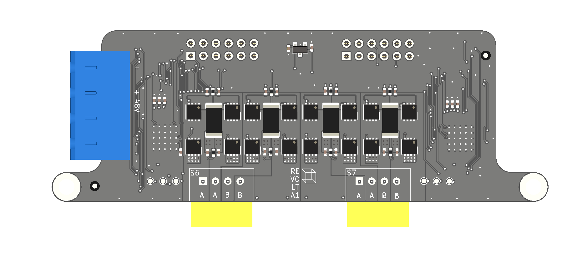
Revolt is a dual 48 V compatible stepper motor driver add-on board. It is based on TMC5160.
Hardware connections
The Revolt add-on baord is designed to stack on top of the Recore A7 board. There are two dual row connectors on the Revolt board, but only one on Recore A7. This means that there is only a software enable/disable for the TMC5160 drivers. It is enabled by default. There is also no diag output from the drivers. Those are broken out on the two other rows and can be connected to pins on the MCU header or DBG header if sensorless homing is required.
Klipper config
This config is using stepper x and y as the high voltage drivers, typical of a core-xy printer setup for speed. This gives the option of having 4 Z-drives and two extruders, 8 steppers in total.
This section sets up the two drivers (X = S6 and Y = S7)
[tmc5160 stepper_x]
run_current: 0.6
hold_current: 0.2
sense_resistor: 0.05
cs_pin: ar100:PD0
spi_software_sclk_pin: ar100:PD2
spi_software_mosi_pin: ar100:PD1
spi_software_miso_pin: ar100:PD3
chain_position: 2
chain_length: 2
stealthchop_threshold: 9999

[tmc5160 stepper_y]
run_current: 0.6
hold_current: 0.2
sense_resistor: 0.05
cs_pin: ar100:PD0
chain_position: 1
chain_length: 2
stealthchop_threshold: 9999
To route step and dir signals to the same motors:
[stepper_x]
step_pin: ar100:PL10
dir_pin: ar100:PE14

[stepper_y]
step_pin: ar100:PL11
dir_pin: !ar100:PE15
Recompiling Klipper
Klipper needs to be recompiled to add software based SPI. Starting with Refactor v3.2.0-RC3
cd /home/debian/klipper
nano src/Makefile
<remove thermocouple.c sensor_adxl345.c and sensor_angle.c>
make menuconfig
<enable Support software based SPI "bit-banging">
make clean
make
mv out/ar100.bin /opt/firmware/
Tuning curves
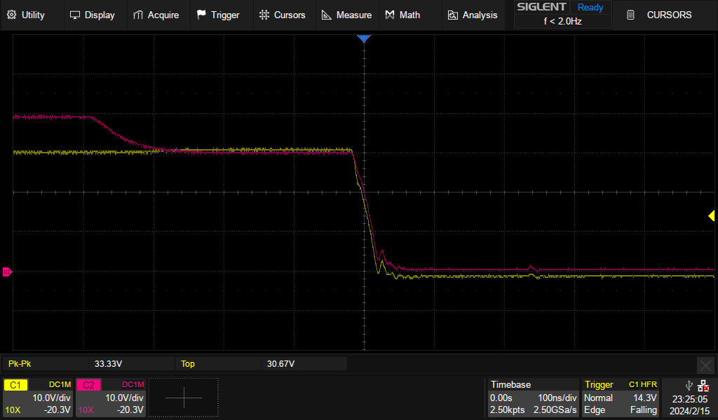
The following oscilloscope capture shows the Revolt A1 running a NEMA 17 stepper at 30 V. The traces are A1 output (yellow) and gate for A1 (pink). The tuning looks good, very little ringing.
Errata
- Plus and minus silkscreen has changed places.
- The enable LED is lighting even though the 24 V input is not present.


