Difference between revisions of "Remove A1"
(Created page with "Remove is an accellerometer for doing input shaping with Klipper. <div class="res-img"> center </div> Klipper configuration: <pre> # The Remove reso...") |
(→Entering boot-mode after flashing) |
||
| (15 intermediate revisions by 2 users not shown) | |||
| Line 1: | Line 1: | ||
| − | Remove is an | + | Remove is an accelerometer for doing input shaping with Klipper. |
<div class="res-img"> | <div class="res-img"> | ||
[[File:Remove A0 iso.jpg|center]] | [[File:Remove A0 iso.jpg|center]] | ||
</div> | </div> | ||
| − | Klipper configuration | + | |
| + | === Pinout diagram === | ||
| + | <div class="res-img"> | ||
| + | [[File:Remove pinout.png|center]] | ||
| + | </div> | ||
| + | |||
| + | === Klipper configuration === | ||
<pre> | <pre> | ||
# The Remove resonance tester mcu | # The Remove resonance tester mcu | ||
| Line 18: | Line 24: | ||
probe_points: | probe_points: | ||
100, 100, 20 # an example | 100, 100, 20 # an example | ||
| + | |||
| + | [static_digital_output remove_leds] | ||
| + | pins: rp2040:gpio17, rp2040:gpio18 | ||
| + | |||
| + | </pre> | ||
| + | |||
| + | |||
| + | === Klipper usage === | ||
| + | To test the accellerometer, try this in the user interface: | ||
| + | <pre> | ||
| + | ACCELEROMETER_QUERY | ||
| + | </pre> | ||
| + | |||
| + | At this time there is an issue with the A1 board where the initialization can fail in Klipper. | ||
| + | |||
| + | If you follow the klipper documentation and run the expected commands you may get the following error: | ||
| + | <pre> | ||
| + | Invalid adxl345 id (got f2 vs e5). | ||
| + | This is generally indicative of connection problems | ||
| + | (e.g. faulty wiring) or a faulty adxl345 chip. | ||
| + | </pre> | ||
| + | |||
| + | This does '''not''' mean your Remove is faulty. Try running the command again, it is a known initialization error, and will go away once the initial message happens. It will happen again next time you restart klipper though, as it re-initializes the ADXL345 again. | ||
| + | |||
| + | After that first test, the actual calibration can be run with: | ||
| + | <pre> | ||
| + | TEST_RESONANCES axis=x | ||
| + | </pre> | ||
| + | |||
| + | Read more on the Klipper pages: [https://www.klipper3d.org/Measuring_Resonances.html#measuring-the-resonances] | ||
| + | |||
| + | === Klipper firmware compilation === | ||
| + | The unit comes with firmware pre-installed. If you want to upgrade the firmware, these are the steps to reproduce. | ||
| + | This can be done directly from Recore, or from a regular computer. If the device ID doesn't match, the board is not in DFU mode, and needs to be manually started that way. Use a paperclip or some wire, unplug the USB of the device, short the two round pads on the back of the PCB and plug in the USB. At that point the RP2040 will be in DFU mode, allowing it to be flashed. | ||
| + | <pre> | ||
| + | cd /home/debian/klipper | ||
| + | cp test/configs/rp2040.config .config | ||
| + | make olddefconfig | ||
| + | make -j | ||
| + | make flash FLASH_DEVICE="2e8a:0003" | ||
| + | </pre> | ||
| + | After that, the board should be visible as OpenMoko, Inc. rp2040 | ||
| + | <div class="res-img"> | ||
| + | [[File:Screenshot from 2024-09-04 18-41-48.png]] | ||
| + | </div> | ||
| + | |||
| + | === Entering boot-mode after flashing === | ||
| + | If a firmware upgrade is necessary, the device must be put into boot mode. This can be done by short together the test points shown below while inserting the USB port. | ||
| + | [[File:Remove pinout back.png|center]] | ||
| + | |||
| + | Or alternatively, you can enter the boot-mode by requesting a baud rate of 1200 | ||
| + | <pre> | ||
| + | picocom -b 1200 <DEVICE> | ||
</pre> | </pre> | ||
| + | More info here: [https://www.klipper3d.org/Bootloader_Entry.html] | ||
Latest revision as of 23:35, 18 November 2024
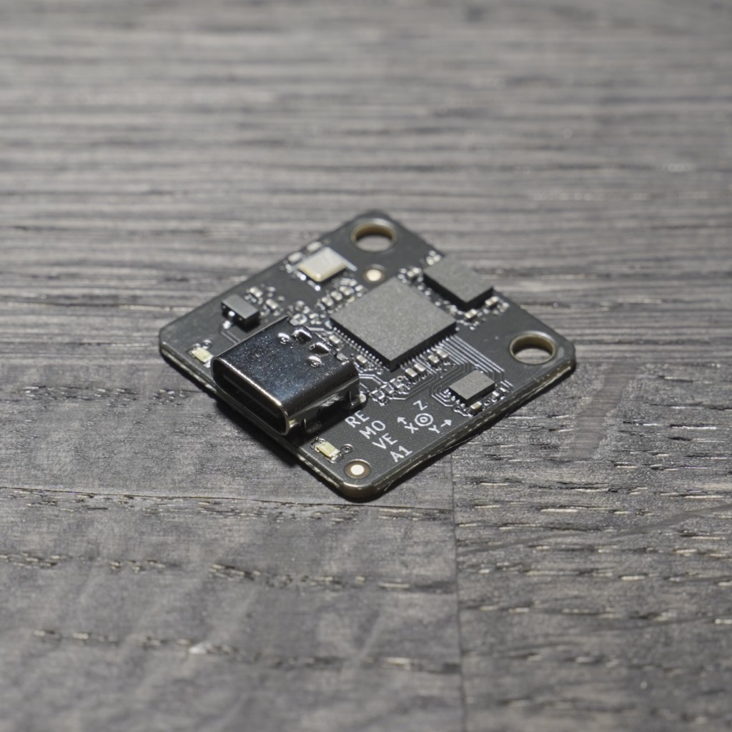
Remove is an accelerometer for doing input shaping with Klipper.
Contents
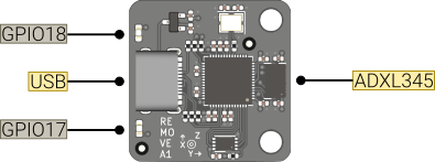
Pinout diagram
Klipper configuration
# The Remove resonance tester mcu
[mcu rp2040]
serial: /dev/ttyACM0
baud: 1500000

[adxl345]
cs_pin: rp2040:gpio5
spi_bus: spi0a

[resonance_tester]
accel_chip: adxl345
probe_points:
    100, 100, 20  # an example

[static_digital_output remove_leds]
pins: rp2040:gpio17, rp2040:gpio18
Klipper usage
To test the accellerometer, try this in the user interface:
ACCELEROMETER_QUERY
At this time there is an issue with the A1 board where the initialization can fail in Klipper.
If you follow the klipper documentation and run the expected commands you may get the following error:
Invalid adxl345 id (got f2 vs e5).
This is generally indicative of connection problems
(e.g. faulty wiring) or a faulty adxl345 chip.
This does not mean your Remove is faulty. Try running the command again, it is a known initialization error, and will go away once the initial message happens. It will happen again next time you restart klipper though, as it re-initializes the ADXL345 again.
After that first test, the actual calibration can be run with:
TEST_RESONANCES axis=x
Read more on the Klipper pages: [1]
Klipper firmware compilation
The unit comes with firmware pre-installed. If you want to upgrade the firmware, these are the steps to reproduce. This can be done directly from Recore, or from a regular computer. If the device ID doesn't match, the board is not in DFU mode, and needs to be manually started that way. Use a paperclip or some wire, unplug the USB of the device, short the two round pads on the back of the PCB and plug in the USB. At that point the RP2040 will be in DFU mode, allowing it to be flashed.
cd /home/debian/klipper
cp test/configs/rp2040.config .config
make olddefconfig
make -j
make flash FLASH_DEVICE="2e8a:0003"
After that, the board should be visible as OpenMoko, Inc. rp2040
Entering boot-mode after flashing
If a firmware upgrade is necessary, the device must be put into boot mode. This can be done by short together the test points shown below while inserting the USB port.
Or alternatively, you can enter the boot-mode by requesting a baud rate of 1200
picocom -b 1200 <DEVICE>
More info here: [2]


