Difference between revisions of "Restep A1"
(→Choosing address) |
(→Mounting it on Recore) |
||
| (5 intermediate revisions by the same user not shown) | |||
| Line 10: | Line 10: | ||
</div> | </div> | ||
| − | === Mounting | + | === Mounting Restep on Recore === |
| − | Restep should be mounted so the stepper is pointing | + | Restep must be mounted in two different ways, depending on how the 6-pin header is soldered. |
| + | # If the pin header is soldered on the component side, the board should be mounted so that the 4-pin header where the stepper motor connects is pointing out the same way as the permanently mounted stepper motors. | ||
| + | # If the pin header is soldered on the bottom of the PCB (where no components are soldered), the 4-pin header where the stepper motor connects should be pointing in towards the center of Recore. | ||
| + | |||
| + | <div class="res-img"> | ||
| + | [[File:Restep mounting.png]] | ||
| + | </div> | ||
=== Choosing address === | === Choosing address === | ||
| Line 18: | Line 24: | ||
It is only necessary to change the address if you are going to use two Resteps on a Recore A6 | It is only necessary to change the address if you are going to use two Resteps on a Recore A6 | ||
</div> | </div> | ||
| − | [[File:Cut here.png|center]] | + | [[File:Cut here.png|thumb|center]] |
If you only have one Restep board mounted on Recore, you do not have to alter it in any way. The default UART address will then be 3. If you want to add one more board, you can cut the lines on AD0 which will give the board address 2. Address 0 and 1 are reserved for stepper 4 and 5 which are mounted on the board on UART3(pins PD0/PD1). | If you only have one Restep board mounted on Recore, you do not have to alter it in any way. The default UART address will then be 3. If you want to add one more board, you can cut the lines on AD0 which will give the board address 2. Address 0 and 1 are reserved for stepper 4 and 5 which are mounted on the board on UART3(pins PD0/PD1). | ||
Latest revision as of 13:31, 21 May 2024
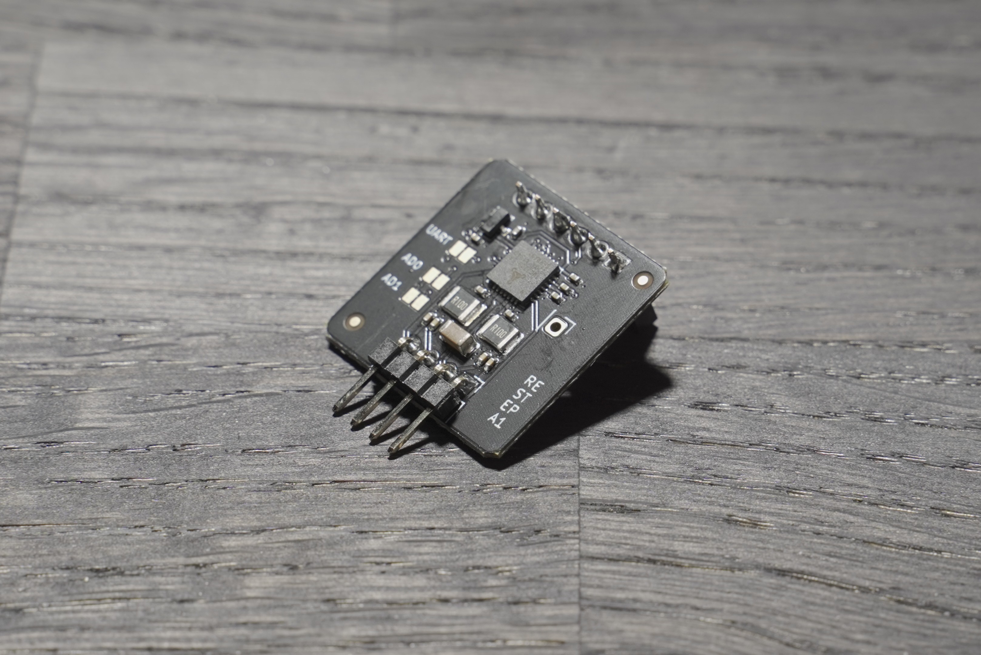
Restep is an add-on board for Recore A6 and Recore A7 which gives it an extra TMC2209 stepper driver. This is great if you want to build a 3D-printer with 7 motors, like the Voron 2.4.
Contents
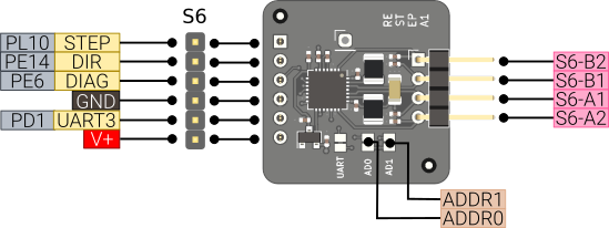
Pinout diagram
Mounting Restep on Recore
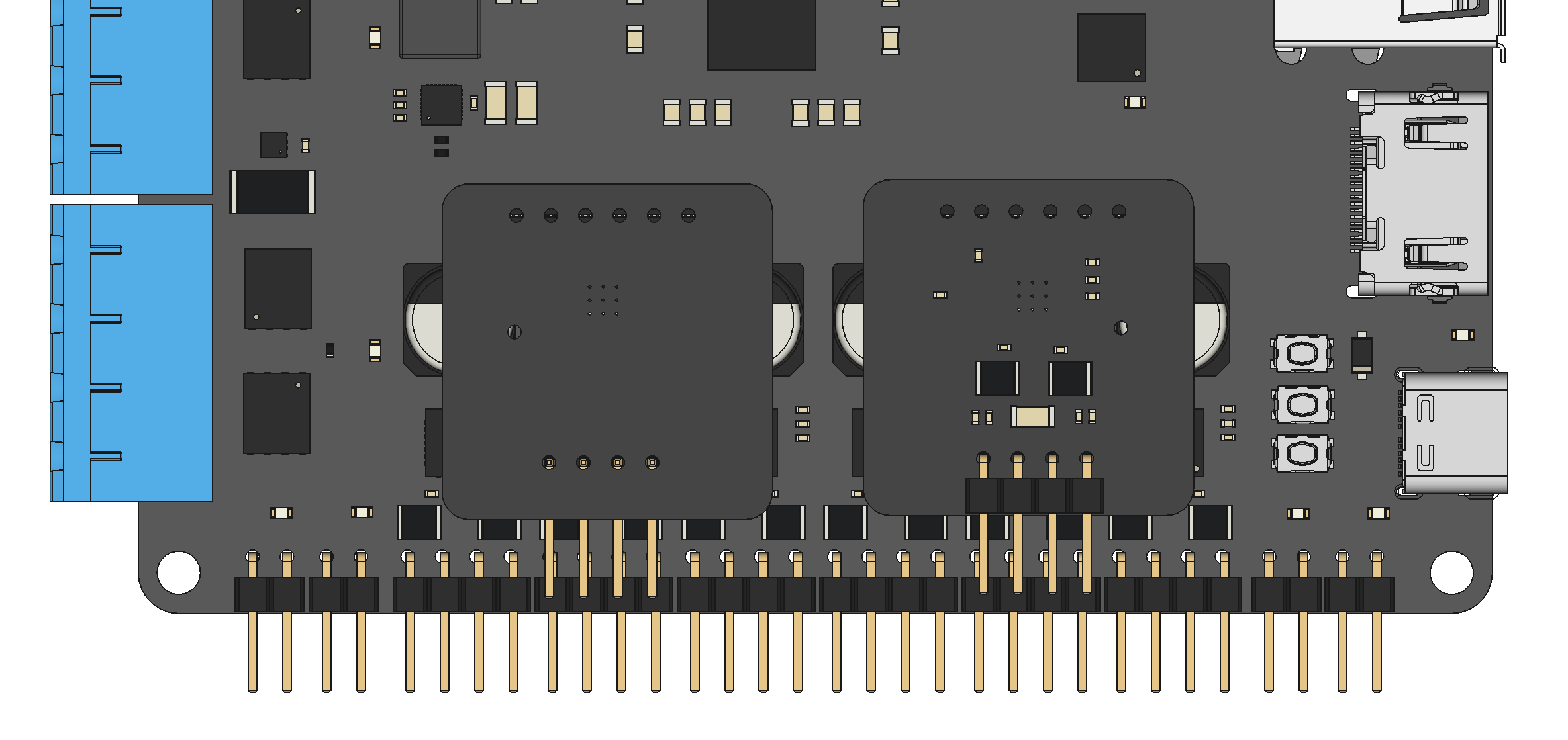
Restep must be mounted in two different ways, depending on how the 6-pin header is soldered.
- If the pin header is soldered on the component side, the board should be mounted so that the 4-pin header where the stepper motor connects is pointing out the same way as the permanently mounted stepper motors.
- If the pin header is soldered on the bottom of the PCB (where no components are soldered), the 4-pin header where the stepper motor connects should be pointing in towards the center of Recore.
Choosing address
Note
It is only necessary to change the address if you are going to use two Resteps on a Recore A6
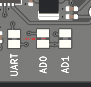
If you only have one Restep board mounted on Recore, you do not have to alter it in any way. The default UART address will then be 3. If you want to add one more board, you can cut the lines on AD0 which will give the board address 2. Address 0 and 1 are reserved for stepper 4 and 5 which are mounted on the board on UART3(pins PD0/PD1).
Klipper Configuration Recore A7
In this example, the X-axis is routed to S6. Only the relevant changes are shown.
[tmc2209 stepper_x]
uart_pin: ar100:PD2
uart_address: 3

# Route stepper X to header S6
[stepper_x]
step_pin: ar100:PL10
dir_pin: ar100:PE14
Klipper Configuration Recore A5 and A6
In this example, the X-axis is routed to S6. Only the relevant changes are shown.
[tmc2209 stepper_x]
uart_pin: ar100:PD1
uart_address: 3

# Route stepper X to header S6
[stepper_x]
step_pin: ar100:PL10
dir_pin: ar100:PE14


