Recore A6
Recore is a 3D-printer control board running Linux. It is specifically tailored to be compatible with Klipper and OctoPrint. The main features are:
- Allwinner A64 SoC, quad core CPU running at 1 GHz.
- 1 GB of DDR3 RAM
- 8 GB of on board eMMC
- Gigabit Ethernet
- 6 TMC2209, 2 A stepper motor drivers
- 3 heater outputs + high power heated bed
- 4 USB High Speed ports
- 4 thermistor/thermocouple inputs (software selectable)
- Comes with Debian Linux with Klipper and OctoPrint installed
This document is for Recore Revision A6. For previous hardware revisions, please see:
Contents
- 1 Availability
- 2 Software release notes
- 3 Schematics
- 4 Pinout
- 5 Wiring
- 6 Klipper Configuration
- 7 Connecting other sensors
- 8 Software for Recore
- 9 Performance
- 10 FAQ
- 10.1 Where can I ask for help?
- 10.2 What comes in the box with the Recore? Specifically, terminal connectors for power, etc?
- 10.3 Do I need access to those 3 buttons on the board?
- 10.4 What's the maximum current draw for heat bed?
- 10.5 Why are there unused and unbroken out pins on the STM32 MCU?
- 10.6 I have a gadget that I want to connect with SPI. Is that possible?
- 10.7 What exactly is the role of the AR100 device?
- 10.8 What voltage fans are supported?
- 10.9 Where is the board layout file?
- 10.10 Where are you shipping from?
- 11 Known hardware issues for rev A6
Availability
Recore A6 can no longer be purchased from the Intelligent Agent web shop https://www.iagent.no/product/recore/ - instead you will receive the newer Recore_A7 or later batch as they become available.
Software release notes
Currently, the latest version to use to flash a Recore A6 is tested as Reflash 0.0.8
The latest recommended versions of Refactor to flash on Recore A6 is ReFactor 3.1.3
Schematics
Recore is "open schematic", it is available here: https://github.com/intelligent-agent/Recore/tree/master/Schematics
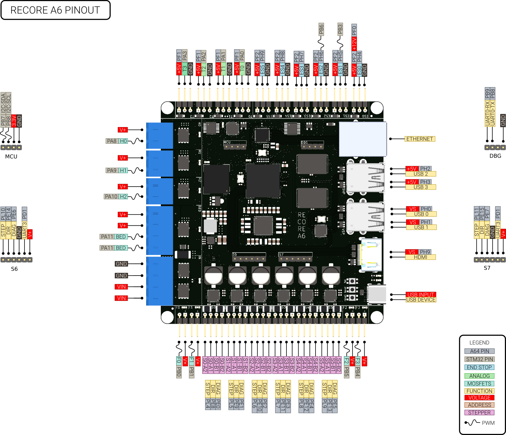
Pinout
A64
The Allwinner A64 is a quad core Cortex A53 clocked at 1 GHz. It has an integrated RISC CPU (AR100) clocked at 300 MHz that handles the real time aspect for the 3D-printer. In the following table the pins used for End-stops and stepper control are described. The "bank and pin" can be used to specify the pin numbers in klipper. The "Number" column is useful for testing things on the command line in conjunction with gpiod.
| Name | Bank and pin | Number | Name | Bank and pin | Number | Name | Bank and pin | Number |
|---|---|---|---|---|---|---|---|---|
| END STOP 0 | PH4 | 228 | DIR 6 | PE14 | 142 | USB-PWR-EN-0 | PH0 | 224 |
| END STOP 1 | PH5 | 229 | DIR 7 | PE15 | 143 | USB-PWR-EN-1 | PH1 | 225 |
| END STOP 2 | PH6 | 230 | STEP DIAG 0 | PE0 | 128 | USB-PWR-EN-2 | PH2 | 226 |
| END STOP 3 | PH7 | 231 | STEP DIAG 1 | PE1 | 129 | USB-PWR-EN-3 | PH3 | 227 |
| END STOP 4 | PH8 | 232 | STEP DIAG 2 | PE2 | 130 | GAIN-ENABLE-T0 | PD4 | 100 |
| END STOP 5 | PH9 | 233 | STEP DIAG 3 | PE3 | 131 | GAIN-ENABLE-T1 | PH11 | 235 |
| STEP 0 | PL4 | 4 | STEP DIAG 4 | PE4 | 132 | GAIN ENABLE T2 | PE17 | 145 |
| STEP 1 | PL5 | 5 | STEP DIAG 5 | PE5 | 133 | GAIN ENABLE T3 | PB2 | 34 |
| STEP 2 | PL6 | 6 | STEP DIAG 6 | PE6 | 134 | PU-ENABLE-T0 | PG10 | 202 |
| STEP 3 | PL7 | 7 | STEP DIAG 7 | PE7 | 135 | PU-ENABLE-T1 | PG11 | 203 |
| STEP 4 | PL8 | 8 | OC-ALERT | PF6 | 166 | PU ENABLE T2 | PG12 | 204 |
| STEP 5 | PL9 | 9 | OC-RESET | PF4 | 164 | PU ENABLE T3 | PG13 | 205 |
| STEP 6 | PL10 | 10 | EN-HP | PF5 | 165 | OFFSET-T0 | PG0 | 192 |
| STEP 7 | PL11 | 11 | UC-INT-1 | PG3 | 195 | OFFSET-T1 | PG1 | 193 |
| DIR 0 | PE8 | 136 | UC-NRST | PG4 | 196 | OFFSET-T2 | PG3 | 194 |
| DIR 1 | PE9 | 137 | UC-BOOT | PG5 | 197 | OFFSET-T3 | PG8 | 200 |
| DIR 2 | PE10 | 138 | ES-EN-12V | PF0 | 160 | STEPPER UART 2 TX | PB0 | 32 |
| DIR 3 | PE11 | 139 | EN-HDMI-PWR | PG9 | 201 | STEPPER UART 2 RX | PB1 | 33 |
| DIR 4 | PE12 | 140 | EN-THERMISTORS | PF1 | 161 | STEPPER UART 3 TX | PD0 | 96 |
| DIR 5 | PE13 | 141 | EN-ENDSTOPS | PF2 | 162 | STEPPER UART 3 RX | PD1 | 97 |
STM32F031
The STM32 is a Cortex M0 powered micro controller handling analog inputs and PWM outputs. It does not control any hard real time aspects of the print, that is handled by the AR100 core realized as a separate core in the A64 SoC.
| Name | Bank and pin | Number | Name | Bank and pin | Number | Name | Bank and pin | Number |
|---|---|---|---|---|---|---|---|---|
| THERMISTOR 0 | PA0 | 6 | HEATER E0 | PA8 | 18 | FAN 0 | PB0 | 14 |
| THERMISTOR 1 | PA1 | 7 | HEATER E1 | PA9 | 19 | FAN 1 | PB1 | 15 |
| THERMISTOR 2 | PA2 | 8 | HEATER E2 | PA10 | 20 | ES1-PWM-OUT | PB3 | 26 |
| THERMISTOR 3 | PA3 | 9 | HEATER BED | PA11 | 21 | FAN 3 | PB4 | 27 |
| BOARD VOLTAGE | PA4 | 10 | USER LED | PA12 | 22 | FAN 2 | PB5 | 28 |
| BOARD CURRENT | PA5 | 11 | PWM-ES2-OUT | PB6 | 29 | |||
| BOARD TEMPERATURE | PA6 | 12 | EXT 1 | PB7 | 30 | |||
| COLD JUNCTION | PA7 | 13 | EXT 2 | PB8 | 32 |
DBG header
This header is used for interacting with u-boot and getting early debug messages from the Linux kernel
| Pin | Function |
|---|---|
| 1 | UART RX |
| 2 | UART TX |
| 3 | NC |
| 4 | GND |
MCU header
This header is used for connecting additional MCU peripherals.
| Pin | Function | Alt |
|---|---|---|
| 1 | PB7 | I2C1_SDA |
| 2 | PB8 | I2C1_SCL |
| 3 | 3.3V | 0.7-3.3V |
| 4 | GND |
LEDs
There are 15 white LEDs on the board. Here is what they mean
| Name | Location | Meaning |
|---|---|---|
| D2 | By PMIC | Board powered |
| D3 | By heater BED | BED output on |
| D4 | By fan 0 | Fan 0 is on |
| D5 | By fan 1 | Fan 1 is on |
| D6 | By heater H2 | Heater H2 is on |
| D7 | By fan 2 | Fan 2 is on |
| D8 | By heater H0 | Heater H0 is on |
| D9 | By fan 3 | Fan 3 is on |
| D10 | By heater H1 | Heater H1 is on |
| D12 | By input connector | High voltage domain is on |
| D15 | By eMMC chip | eMMC activity |
| D17 | By HDMI connector | USB activitiy |
| D18 | By the USB C connector | Linux Heartbeat |
| D19 | By the A64 SoC | CPU activity |
| D20 | By the STM32 | Klipper running on STM32 |
Buttons
There are 3 push buttons on the board.
| Name | Meaning |
|---|---|
| FEL | Enter FEL-mode of the A64 |
| BOOT | Boots or shuts down the board |
| RESET | Hard reset of the CPU |
Current limits
| Name | Limit |
|---|---|
| 5V-ES | 0.75 A |
| USB host each | 1.0 A |
| Thermistors | 0.75 A |
| MCU connector | 0.5 A |
| Fan connectors | programmable |
| Heater connectors | programmable |
Wiring
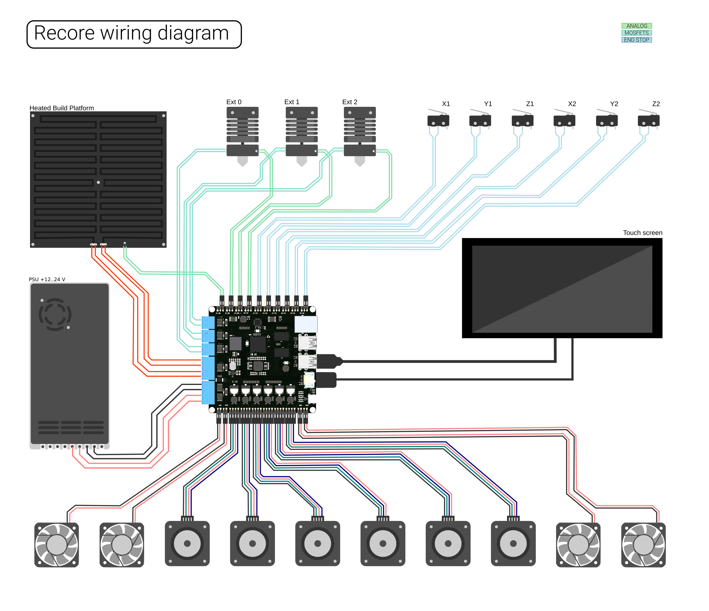
Below is a wiring diagram meant to aid in connecting motors, fans, extruders and hot ends to the control board. On the board, there is a small + sign next to output connectors where polarity is important. If passive heating elements are used, polarity is not important, but if those outputs are to be used with SSRs or relays, polarity must be observed.
Network connection
Recore is designed to be controlled through a browser on a computer, so the board must be connected to the local LAN or wifi network. Connect an ethernet cable between the board and a switch. The ping utility can be used to ensure that the board is discovered on the network.
LAN setup
Recore with Refactor is running avahi and should announce itself on the network once a connection has been established. On a Linux based host computer, it is possible to search for a booted device using the following command:
ping recore.local
If the device is present, an SSH connection can be established:
ssh root@recore.local
Furthermore, a web interface running OctoPrint can be found using a browser:
Wifi setup
Wifi can be set up by connecting a wifi dongle to one of the USB host ports. Once the uSB dongle has been connected, and the board has been booted, access to the terminal command line can be given through a host computer. The board should appear as a TTY ACM device. On a Linux based host computer, the terminal program `screen` can be used to get access. From the host computer
screen /dev/ttyACM0 115200
If the host computer is running Windows, Putty can be used to get access.
Once a connection has been established, the wifi network can be set up using the command nmtui.
nmtui
Follow the instructions on screen to edit and activate the wifi connection.
Note
If the board is powered through the USB C connector, only the two USB host ports next to the HDMI port is powered. See also known hardware issues at the bottom of this page.
Mating Connectors
The power connectors on the board are available either in the web shop as part of a connector pack or directly from Digi-key etc.
Four pin male: TBP01P1-508-04BE [| Digi-key]
Two pin male: TBP01P1-508-02BE [| Digi-key]
Klipper Configuration
There are no jumpers on Recore and no hard fuses. Everything is software configurable and resettable from software. This gives great power and flexibility without requiring physical access to the board once it has been installed. But with great power comes great responsibility. It is possible to break things if care is not taken during setup. There is one setting in particular that is worth mentioning: ES0 can have either +5V or +12V on the power pin. This is in order to allow a standard industrial inductive sensor to be used on that end stop. If a 5V only peripheral is connected, that could damage the connected peripheral.
The default config file for Recore A6 can be found in the repository: generic-recore-a6.cfg
TMC2209
The 6 stepper drivers on Recore are of type TMC2209 from Trinamic. Each stepper has a configuration interface with a bidirectional UART port that is connected to a peripheral UART on the A64. The peripheral is not in use, but instead the GPIO bit-banging functionality of Klipper is used to communicate with the stepper drivers.
Here is a table with pins and addresses for the steppers
| Stepper driver config | ||
|---|---|---|
| Name | Pins | Address |
| S0 | PB0/PB1 | 0 |
| S1 | PB0/PB1 | 1 |
| S2 | PB0/PB1 | 2 |
| S3 | PB0/PB1 | 3 |
| S4 | PD0/PD1 | 0 |
| S5 | PD0/PD1 | 1 |
| S6 | PD0/PD1 | 2 |
| S7 | PD0/PD1 | 3 |
External stepper drivers
It is possible to connect up to two external stepper drivers to Recore in addition to the 6 divers installed on the board. These can be connected using the headers S6 and S7.
Temperature inputs
4 different temperature devices can be connected to the 4 analog inputs on Recore. Thermistor, Thermocouple, PT100 with INA826 and PT1000 without the use of a pre-amplifier.
Thermistor
Make sure the pull-up is enabled and the op-amp gain is set to 1.
Thermocouple
Make sure the pull-up is disabled and the op-amp gain is set to 100.
[recore]
...
gain_t0: 100
pullup_t0: 0
offset_t0: 1

[Extruder]
...
sensor_type: Type K
PT100 with INA826
In order to use a PT100 sensor, an external amplifier board must be used. There is an example configuration for Klipper that uses this. The ADC reference voltage is 5.0 by default, but for Recore it is 3.3 V. Here is an example:
[Extruder]
...
sensor_type: PT100 INA826
adc_voltage: 3.27
The pull-up must also be disabled.
PT1000
Make sure the pull-up is enabled and the gain is set to 1. In the latest version, the sensor must be prefixed with RECORE.
[Extruder]
...
sensor_type: PT1000
pullup_resistor: 4750
Connecting other sensors
The board has been designed to work with a range of 3rd party sensors for automating the print.
BLtouch
There are two versions of the BLtouch, the difference is the color of one of the GND wires.
The Creality version has a blue GND wire.
Note
There have been some cases of bad quality control for the Creality BLTouches, where the pinout on the sensor side have not matched the color coding in the photos/documentation. It might be good to make sure the color codes match up. For the Creality it should be, from left to right: Blue, red, yellow, black, white.
When connected per wiring diagram above, setting up BLtouch can be done by adding the following section to printer.cfg.
[bltouch]
sensor_pin: ar100:PH6
control_pin: !PB3
speed:15
samples:1
pin_move_time: 0.675
sample_retract_dist: 10
probe_with_touch_mode: true
stow_on_each_sample: false
x_offset:29.2
y_offset:-34
z_offset:0
Inductive Sensor
Connect the inductive sensor on ES0. You can choose either 5V or 12V output on the voltage pin. Inductive sensors often come with an industry standard voltage input of 6-36 V. For this reason there is a 12 V LDO (Low drop-out) voltage regulator integrated on the board. This voltage regulator can be output on the V+ pin of the connector marked ES0. If the Input to the board is 12 V, the LDO will supply a lower voltage, around 10.6 or so.
ADXL345
Note
The ADXL345 seems to cause Klipper to shut down when trying to calibrate at a high rate. A workaround is to use a Pi Pico or similar MCU to communicate with the ADXL345, or to lower the rate. It's been tested working at 400, but not 800 which is the recommended minimum.
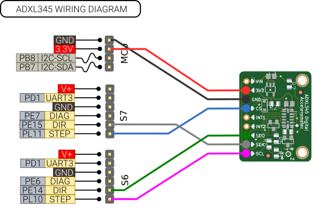
A popular accelerometer sensor for doing input shaping with Klipper is the ADXL345. This can be connected to the connectors S6/S7. There is no hardware SPI interface available, but a software implementation in Klipper exists. Note: Only experimental support has been tested for this. https://learn.adafruit.com/adxl345-digital-accelerometer
Config:
[adxl345]
cs_pin: ar100:PL11
spi_software_sclk_pin: ar100:PL10
spi_software_mosi_pin: ar100:PE15
spi_software_miso_pin: ar100:PE14
rate: 400

[resonance_tester]
accel_chip: adxl345
probe_points:
    100, 100, 20  # an example
Using a Raspberry Pi Pico:
[adxl345]
cs_pin: pico:gpio17
spi_bus: spi0c
RC Servo
Endstop 1 and 2 can be used as PWM outputs with 5V levels. Rev A6 is the first board with support for this. More testing and configuration documentation is needed.
Filament runout sensor
Any of the 6 end stops can be used for connecting a filament runout sensor
Software for Recore
Recore comes with the Linux distro Refactor (Armbian) pre-installed on the eMMC. For more instructions about software for Recore, see the Refactor wiki page: Refactor#Recore
AR100
Please see: AR100
Manual control and testing
https://wiki.iagent.no/wiki/Manual_control_and_testing
Performance
Start-up time
With a maximum clock for MMC2 of 200 MHz, here is the start-up time:
root@recore-3:~# systemd-analyze
Startup finished in 5.128s (kernel) + 11.567s (userspace) = 16.695s
graphical.target reached after 11.421s in userspace
Measured voltages
The final stages of Recore manufacturing consists of testing, calibration and flashing of firmware. The calibration stage measures a number of voltages on the board and classifies the input stages gain and offset. Instruments used:
- HP 3458A, 8.5 digit multimeter
- HP 3245A, Universal Source
Microcontroller voltages
VDDA uC: 3.312 V
VDD uC: 3.312 V
Voltage from the PMIC supplied as bias:
0.706 V
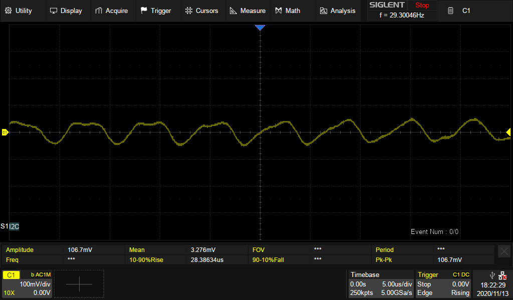
5V Buck converter ripple and noise
The 5V step down/Buck converter is a AOZ2151PQI-10. It can provide 4A and has an input voltage range of 12-28V. It is hard wired to be in PWM mode. PFM mode results in a loud whine.
Below is a screenshot of the ripple and noise across the the 5V rail with a normal kernel running.
Input stage
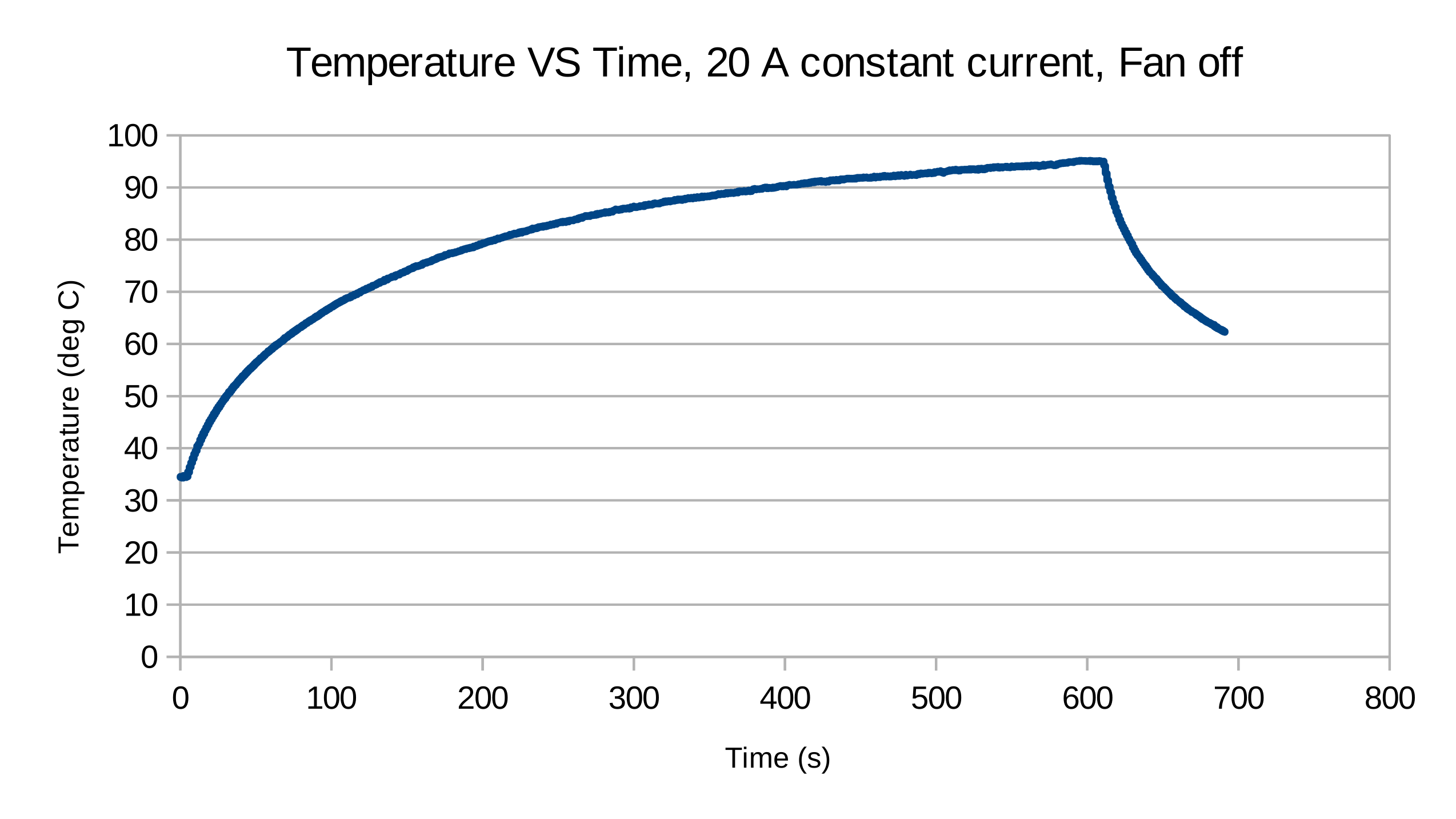
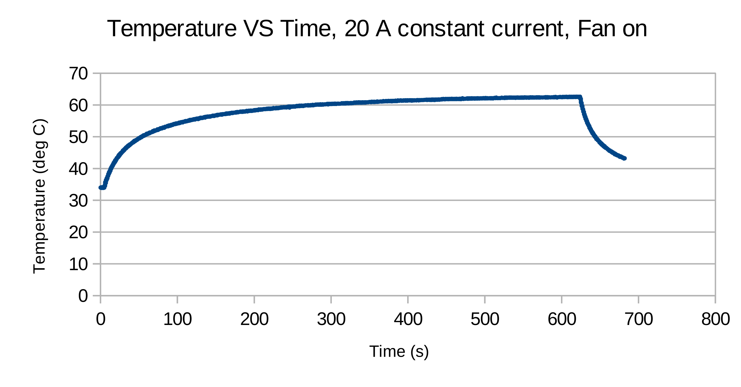
An experiment with a constant current load drawing 20 A from the bed connector with and without a 92 mm fan on top of the board for forced convection. The temperature measured was with the on board thermistor. Using a thermal camera, the temperature displayed matches well with the temperature reported by the camera. However, in Rev A2, this is not the hottest point on the board. The MOSFET controlling the bed seems to consistently get the highest temperature. The reason for this is probably due to a 3.3 V VGS.
Inrush current
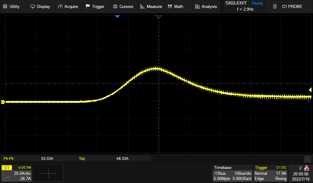
During turn on of the high power stage, there will be an inrush current to charge up the bank of capacitors present on the board. If no loads are turned on, the inrush current reaches 48 A at peak. This is important to consider when setting the current limit with device tree. Below is a trace of the current draw of Recore A6 when the input is enabled.
There are 3 different sensors present in the input stage for making sure the 12-24 V domain on the board does not overheat during startup and operation.
- The Fast acting over current protection is to ensure that the high power domain is disabled in the case of a short circuit condition.
- The current limit set in Klipper monitors the continuous current draw. This is now set at 20 A, but can go up to 30 A and still be within the limits of the connectors and input stage mosfets.
- The over temperature protection monitors the temperature in the input stage and cuts the power if the temperature goes over 110 degrees. The board should not be kept at this temperature for a prolonged period, but during heated bed heat-up, it can be elevated compared to the rest of the print.
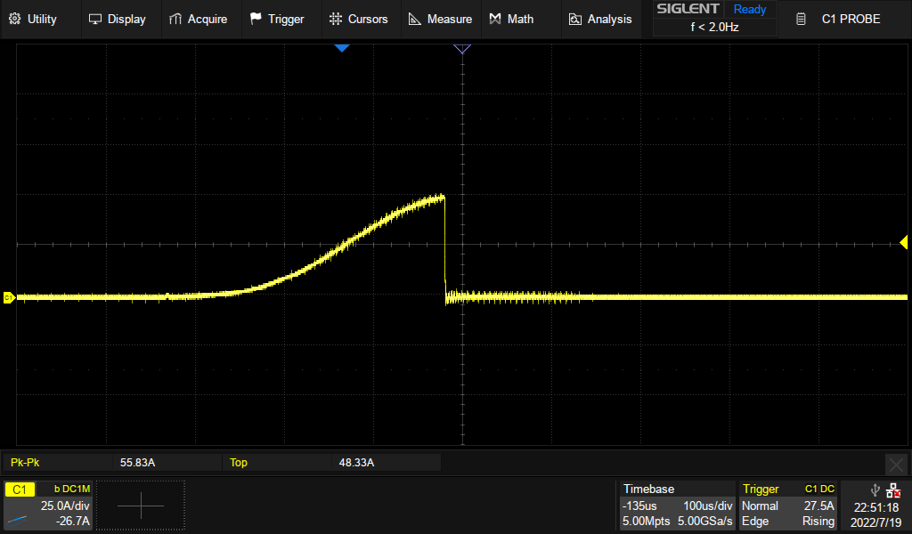
Below is a plot of what the current on the input looks like if there is an over current condition on the high power domain as that domain is turned on.
ADC offset and gain measurements
To measure the ADC offset error, measure the voltage on the uC input pin and record when the transition from 0 to 1 occurs. It should occur at 0.5 LSB = 3.3/4096/2 = 0.4028 mV. Offset: 55.35 mV - 0.4028 mV = 54.95 mV
Temperature calibration
A set of experiments have been carried out to calibrate the different sensors using a dry-well calibrator. The reference probe was a Sensing Devices SDL385 PRT. The levels of calibration was: room temperature, 50, 100, 150, and 200 degrees C.
Thermistor
The thermistor in use was a standard EPCOS 100K B57560G104F. This thermistor has a resistance tolerance of 2 %. The value of the pull-up resistor as measured during calibration was 4740.17501. This value seemed to work well at all levels of calibration, although a little on the high side compared to the reference.
PT1000
The PT1000 in use was a Heraeus 31500989 [1] works well. The tolerance class given in the datasheet is "F 0.10 / Class 1/3 B". There are two different tolerances here: F0.10 and one third of Class B. The accuracy looks good at all temperatures, perhaps a bit on the high side if using the calibrated value for the pull-up. During the testing, 10 ohm was subtracted from the calibrated value.
PT100
The PT100 used in the calibration was the E3D PT100 with the INA826 amplifier board. There is no datasheet available for the PT100 sensor and no mention of what tolerance there is on the reference resistors used. Furthermore Klipper expects the reference voltage to be 5V exactly, and there is no way to supply a measured value. Measurements on Recore has shown that the value is often a bit lower due to the PMIC for the 5V output on the "input" ports. 4.979 V has been measured and is likely an expected value.
Thermocouple
Using the calibration values directly will give a slight offset to the thermocouple measurements. The gain and ADC voltage can be used as measured during calibration. It should be in the region of 101 for gain and 3.307 for ADC voltage. As for the offset, that can be increased slightly to compensate for the cold junction temperature difference. For instance, the measured offset for the test board was 0.0032960, but a value of 0.00340 fit the data points well. The measurements were done on T2, so it it possible that the distance from the cold junction caused the offset. The cold junction thermistor is located between T0 and T1.
FAQ
Where can I ask for help?
- You can join the Discord: https://discord.gg/bCnp9H5SB5
What comes in the box with the Recore? Specifically, terminal connectors for power, etc?
- It's only the board, no cables or connectors. There is a bag of connectors available to purchase in the web shop.
Do I need access to those 3 buttons on the board?
- It is not necessary to have access to the three buttons for normal use.
What's the maximum current draw for heat bed?
- This has been tested up to 20 A
Why are there unused and unbroken out pins on the STM32 MCU?
- The pins that are needed from the MCU have been routed out plus two pins available on an external header.
I have a gadget that I want to connect with SPI. Is that possible?
- There are 6 pins available from the main SoC that can be used for various things.There is no hardware SPI, but you can make a program that uses soft SPI. There is no dedicated I2C, but perhaps that would be a nice addition.
What exactly is the role of the AR100 device?
- The AR100 handles the fast real-time aspects, mainly the stepper motors and end stops.
What voltage fans are supported?
- The same voltage as the input voltage, either 12 V or 24 V. You can experiment with PWM for running lower voltage fans on 24 V input.
Where is the board layout file?
- The Layout file will not be available. It is an "open schematic" board, not open source hardware
Where are you shipping from?
- Boards are shipping from Norway. Eventually shipping will be from a warehouse in the US
Known hardware issues for rev A6
T1 offset is not consistent
- On Rev A6, during calibration it has been discovered that the offset on T1 is often varying around the predetermined set point of 0.33 V. It seems the cause of this is the batch of op-amps used, so it is a hardware issue. The good news is that it seems to be OK to use the values from the calibration document. The gain should be about the same (101).
Board can not handle 24 V input (fixed)
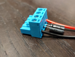
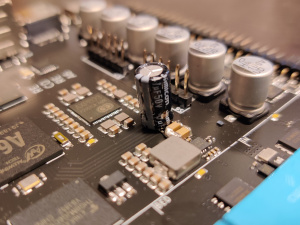
- The design without alterations can not handle 24 V input. A bare board can only handle about 20 V. A workaround is to add an electrolytic capacitor to the input. This can either be soldered on to the step down converter input MLCC capacitors, or it can be screwed directly on to the input connector. Be aware of the polarity of the capacitor when mounting it. The "minus" should be towards the black wire. The recommended value is a 47 uF capacitor with a voltage rating of 35 V or higher. 33 uF has also been tested and working. 100 uF and higher should also work, but has not been tested specifically.
- The capacitor that will be added to remaining boards from the Rev A6 batch is ESH476M035AE3AA from Kemet: https://www.digikey.com/en/products/detail/kemet/ESH476M035AE3AA/2712504
- It seems the reason for the issue is a combination of long wires with high inductance, too low capacitance on the input of the board and too little headroom on the step down converter. This can cause voltage spikes that makes the input voltage go above the rated input voltage during load changes. Adding a capacitor to the input "buffers" or "decouples" the long inductance wires and limits the voltage spikes.
USB connectors not discovered when powered by USB device (workaround)
- Some boards are not initialized right when powered by only the USB port. The reason for this is that the VBUS/over current input on the USB hub can get an ambiguous value from USB connector 2 and 3 (the two USB host connectors close to the ethernet connector).
- A workaround is to apply power to the VIN (12-24V) connector first. If FEL-mode is necessary, that button must be pressed as power is applied from the VIN connector. After that the USB connector can be inserted.


