Recore A2
This page is for Recore Revision A2, check out Recore for the latest info.
Contents
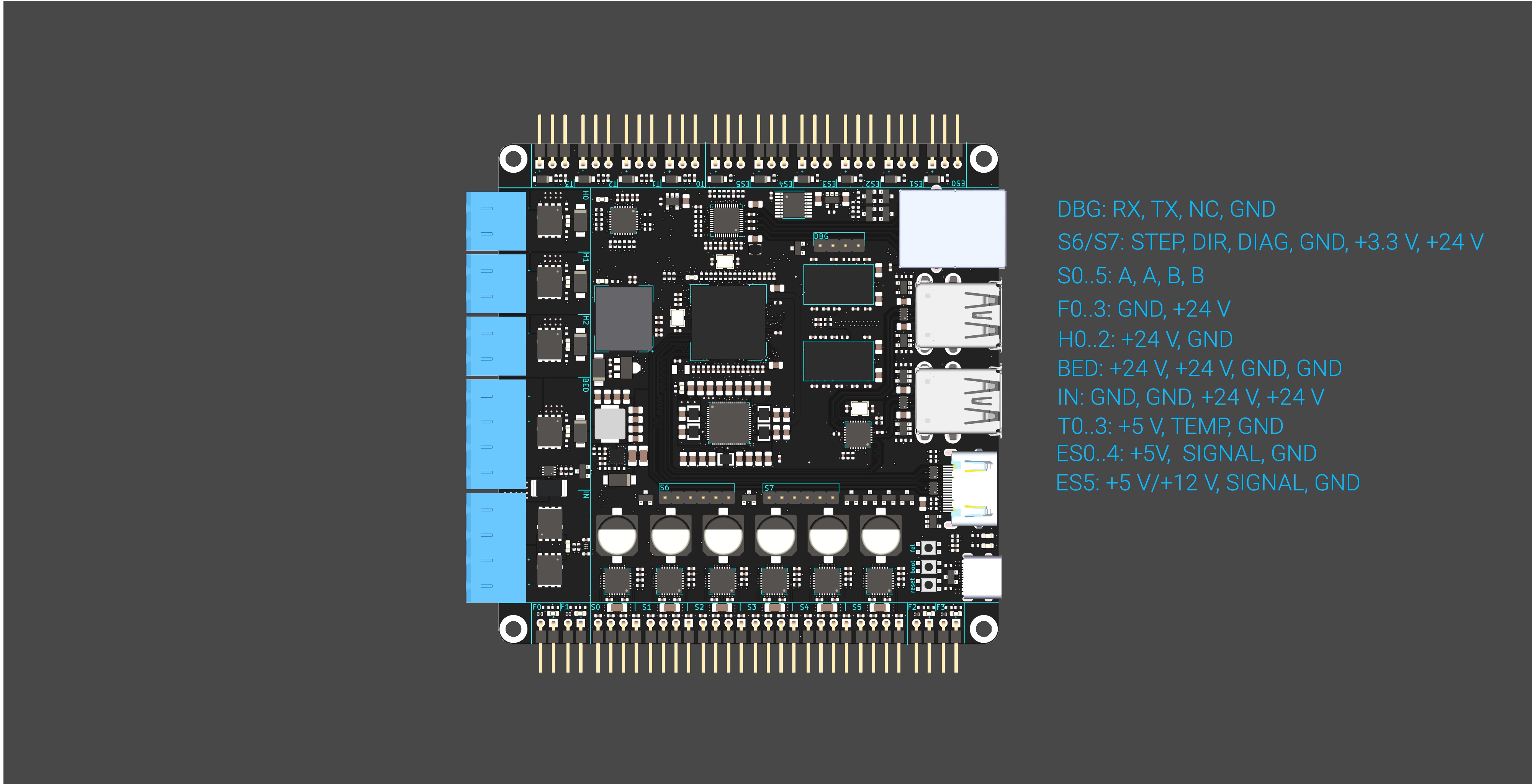
Hardware overview
Software for Recore
Distro
Starting with Armbian Buster Server for Pine 64 (kernel 5.4) https://dl.armbian.com/pine64/Buster_current Flash the software to a USB drive.
Once flashed, it's necessary to add the Recore device tree to the right folder.
cp sun50i-a64-recore.dtb /media/xxx/boot/dtb/allwinner/
With a clean board, it's necessary to start the board from a host computer using FEL mode.
sunxi-fel -v -p spl sunxi-spl.bin write 0x44000 bl31.bin write 0x4a000000 u-boot.bin reset64 0x44000
The output will appear in teminal UART0. You can use minicom on a host computer to watch the boot process and get a login screen
minicom -D /dev/ttyUSB0 -w
If a dongle with Armbian is present in one of the USB host slots, it should boot from the dongle.
Booting from USB if an OS is present on the eMMC
If the eMMC is parititioned and has an OS, u-boot will launch right into that. In order to override that and boot from a USB dongle, stop u-boot by pressing a key and then write:
setenv devnum 0
run usb_boot
Install distro to eMMC
Create Partition:
export card=/dev/mmcblk0
blockdev --rereadpt ${card}
cat <<EOT | sfdisk ${card}
1M,,L
EOT
mkfs.ext4 ${card}p1
Copy Kernel and rootfs to eMMC
Use the flash script in Redist
mount /dev/mmcblk0p1  /mnt/
rsync -aAx --human-readable --info=name0,progress2 --exclude={/dev/*,/proc/*,/sys/*,/tmp/*,/run/*,/media/*,/mnt/*,lost+found/} /* /mnt
echo "rootdev=/dev/mmcblk0p1" >> /mnt/boot/armbianEnv.txt
Update the UUID in fstab to the UUID of the eMMC part 1
export UUID=`blkid | grep mmcblk0p1 | awk -F'"' '{print $2}'`
sed -i "s/UUID=.*\//UUID=$UUID \//g" /mnt/etc/fstab
Make eMMC bootable (WIP)
Place U-boot-spl in sector 15 (8KB offset) Clean card:
dd if=/dev/zero of=/dev/mmcblk0 bs=1k count=1023 seek=1
Flash the binary
dd if=u-boot-sunxi-with-spl.bin of=/dev/mmcblk0 bs=1024 seek=8 conv=notrunc
The board (A2) does not boot using this technique. It looks like ALDO1 used to power the eMMC IO (VCCQ) is not on by default. The CMD line also needs a pull-up. Maybe also a pull-down on DS.
Note: U-boot needs to be patched in order to use the eMMC as the first (and only) boot device. The changes can be done in "spl_mmc_get_device_index" where dev_num should be 0 instead of 1.
Install Klipper
It's good to add a separate user for Klipper:
useradd klipper -s /bin/bash -G sudo,dialout
passwd klipper
mkdir /home/klipper
chown klipper:klipper /home/klipper
su klipper
cd ~
git clone https://github.com/intelligent-agent/klipper
cp klipper/config/generic-recore.cfg ./printer.cfg
./klipper/scripts/install-ubuntu-18.04.sh
You can check the log by writing
tail -f /tmp/klippy.log
Install STM32 firmware
This flash scripts requires gpiod
sudo apt install gpiod
cd /home/klipper/klipper
cp .config_stm32 .config
make
sudo ./scripts/flash-stm32.sh out/klipper.bin (might have to be run several times)
Install AR100 firmware
The ar100 needs to be compiled on an x86_64 computer. The reason for this is the lack of an or1k toolchain for aarch64. On a host computer:
cp .config_ar100 .config
make
scp out/ar100.bin root@recore.local:/home/klipper/klipper/out/
On the Recore board:
sudo /home/klipper/klipper/scripts/flash-ar100.py /home/klipper/klipper/out/ar100.bin
Running Klipper
After a reboot, the ar100 firmware needs to be reflashed. We will get this into an automatic routine eventually, bit for now:
sudo /home/klipper/klipper/scripts/flash-ar100.py /home/klipper/klipper/out/ar100.bin
Giving right privileges for AR100 restart
The AR100 flasher and reset script needs to be run as root. We create a group called flashers, add klipper to that and gie the group sudo access to the script
sudo addgroup flashers
sudo adduser klipper flashers
echo '%flashers ALL=(ALL) NOPASSWD: /home/klipper/klipper/scripts/flash-ar100.py *, /usr/bin/gpioset *' > /etc/sudoers.d/flashers
Install Octoprint
su klipper
cd ~
sudo apt update
sudo apt install python-pip python-dev python-setuptools python-virtualenv git libyaml-dev build-essential
mkdir OctoPrint && cd OctoPrint
virtualenv venv
source venv/bin/activate
pip install pip --upgrade
pip install octoprint
./venv/bin/octoprint serve
Add a systemd start-up script
nano /lib/systemd/system/octoprint.service
Add the following content
[Unit]
Description=The snappy web interface for your 3D printer
After=network-online.target
Wants=network-online.target

[Service]
Type=simple
User=klipper
ExecStart=/home/klipper/OctoPrint/venv/bin/octoprint

[Install]
WantedBy=multi-user.target
Enable and start script
sudo systemctl enable octoprint
sudo systemctl start octoprint
Manual control and testing
To use the examples in this section, first install gpiod
apt install gpiod
Power domains
There are 9 power domains around the board controlling voltage on different pins:
- Input power controls power to 4 high power outputs, the 4 fans and the 6 stepper drivers. This input has current monitoring, fast acting over current protection, voltage monitoring, temperature monitoring and reverse polarity protection.
- Thermo couple power Controls +5V/1A output to the ADCs. This can be used for turning on power to the analog pins.
- End stop power Controls +5V/1A output on the six endstops. Ganged. ES5 can be switched to have 12V output. The 12V output has a
100mA internal current limit.
- 4 USB host power domains Controls 5V/1A current output to the usb host connectors. These are turned on by u-boot.
- HDMI 5V output Controls the 5V/1A HDMI output. Turned on by u-boot.
Input stage
Reset over current protection and set it in "one-shot" mode.
gpioset 1 193=0
gpioset 1 193=1
The over current protection can also be set in "transparent" mode, where the current alarm will be reset automatically. Note that this is a bad idea for general operation, only use for testing.
gpioset 1 193=0
Enable 24V input
gpioset 1 194=0
End stop 5V /12V
End stop 0 to 4 has a programmable +5V output voltage. End stop 5 has +5V or +12V selectable.
To enable +5V on ES 0...4
gpioset 1 203=1
To disable again
gpioset 1 203=0
To switch to 12V output on ES5
gpioset 1 199=1
To disable again
gpioset 1 199=0
End stops values
To see what value the end stops have
gpioget 0 2 # ES 0
gpioget 0 3
gpioget 0 4
gpioget 0 5
gpioget 0 6
gpioget 0 7 # ES 5
TMC2209
In window/shell 1:
stty -F /dev/ttyS2 raw -echoe -echo
xxd -c 4 /dev/ttyS2
In window/shell 2:
echo -n -e '\x5\x0\x6\x6F' > /dev/ttyS2
The return should be along the lines of
00000000: 0500 066f  ...o
00000004: 05ff 0620  ...
00000008: 0001 4058  ..@X
To read the OTP registers
echo -n -e "\x5\x0\x5\x21" > /dev/ttyS2
echo -n -e "\x5\x0\x5\x21" > /dev/ttyS3
echo -n -e "\x5\x1\x5\x97" > /dev/ttyS2
echo -n -e "\x5\x1\x5\x97" > /dev/ttyS3
echo -n -e "\x5\x2\x5\x7a" > /dev/ttyS2
echo -n -e "\x5\x2\x5\x7a" > /dev/ttyS3
echo -n -e "\x5\x3\x5\xcc" > /dev/ttyS2
echo -n -e "\x5\x3\x5\xcc" > /dev/ttyS3
To set the OTP register to use RDSon:
echo -n -e "\x5\x0\x84\x0\x0\xbd\x6\xac" > /dev/ttyS2
STM32F031
There is a small firmware to test all functionality that is controlled by the STM32F031 chip on the board. Once uploaded to the board using the flash script, the firmware will turn on all LEDs it controls and send back ADC readings.
To flash this firmware to the STM32:
gpioset 1 197=1
gpioset 1 196=0
stm32flash -i -196,196 -w Sumato-f031.bin -v -g 0x00 /dev/ttyS1
gpioset 1 197=0
stm32flash -i -196,196 /dev/ttyS1
To see the ADC readings:
stty -F /dev/ttyS1 38400 raw
cat /dev/ttyS1
You should see something like
ADC T0: 0
ADC T1: 0
ADC T2: 0
ADC T3: 0
ADC U: 2338
ADC I: 0
ADC TB: 3417
The following one-liners assumes gawk is installed.
You can convert the current (as in amps) reading to something useful like this
cat /dev/ttyS1 | awk '/I:/ { printf "scale=4; (%i/4096)*132\n", $3; fflush(); }' | bc -l
To see the temperature readings, try this :
cat /dev/ttyS1 | awk '/TB:/ { printf "scale=4; 4308/l( (4700/((3.3/(3.3*%i/4096))-1.0))/0.05306820342563400000) -273.15\n", $3; fflu
sh(); }' | bc -l | awk '{print strftime("%k:%M:%S"), $0; fflush();}'
HDMI power
echo 201 > /sys/class/gpio/export
echo out > /sys/class/gpio/gpio201/direction
echo 1 > /sys/class/gpio/gpio201/value
AR100
See also: AR100
Loading a binary into SRAM A2
Get Crust in order to load the AR100 bin file into memory
git clone https://github.com/intelligent-agent/ar100-fw
cd ar100-fw
make defconfig
HOST_COMPILE= make tools
Once the load program is compiled, an AR100 binary blob can be loaded with
./ar100-fw/build/tools/load scp.bin
Please note that the AR100 binary file bust be 8 byte aligned, meaning that the size must be divisible by 8.
Known Issues
Linux
The default config option for Pine64 seems to be a maximum of 4 uarts. In order to increase that, it is necessary to compile a new kernel.
Rev A2
This revision was sent out to two beta testers. Not put into production.
Ethernet slow at appearing
Ethernet sometimes uses a long time to come up.
Reset button not responding
Simply pressing the reset button does not always cause a reset of the board.
eMMC can not run at full speed
HS200 does not seem to work, this might be related to data line length mismatch.
Can not boot from eMMC
HDMI not always appearing
On-board thermistor source impedance
The on-board thermistor chosen for A2 is 100 K, which in conjunction with the 4.7 K pull-up causes the source impedance to be above the recommended 50 K external input impedance. (100 K sinking) When sampling the value from the on-board thermistor, the ADC is loaded too much causing a dip in the value. The result is that a lower value sampled than what is actually present on the ADC pin. If the sample time is kept at minimum (1.5 cycles) the offset will be large. Increasing the sample time fixes that problem. File:SDS5034X PNG 68.png
Performance Testing
Measured voltages
Measurement instrument: Siglent SDM3065X, 6.5 digit multimeter
Microcontroller voltages
VDDA uC: 3.312 V
VDD uC: 3.312 V
Input stage
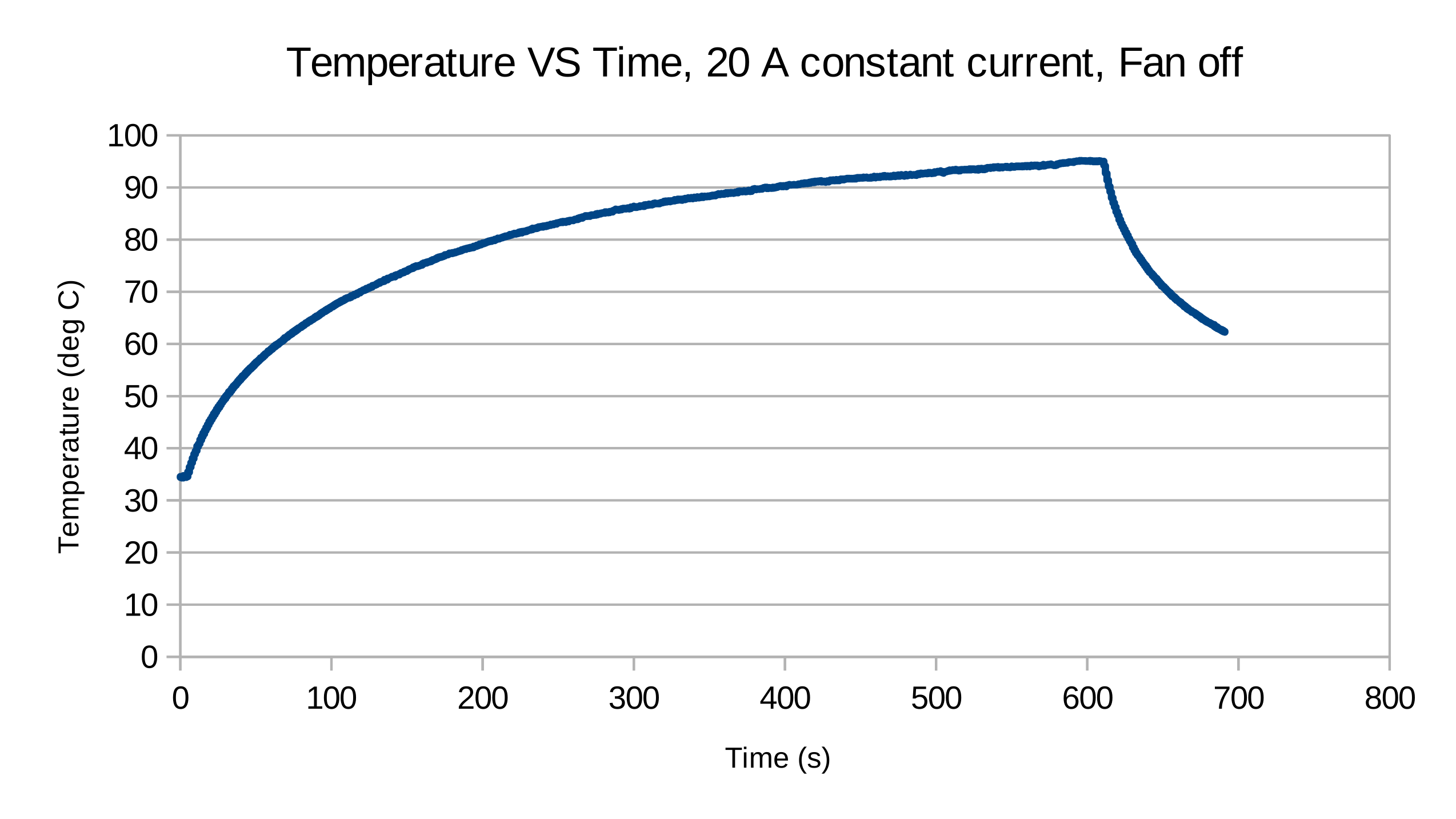
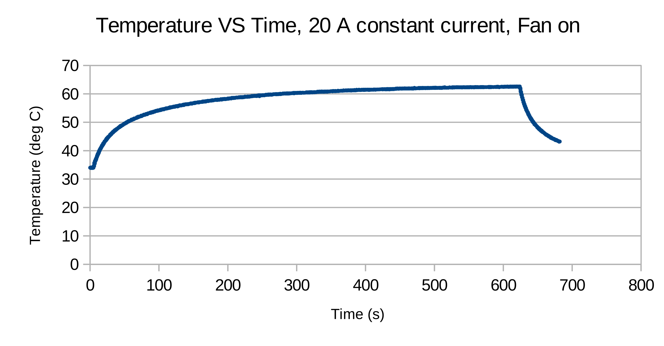
An experiment with a constant current load drawing 20 A from the bed connector with and without a 92 mm fan on top of the board for forced convection. The temperature measured was with the on board thermistor. Using a thermal camera, the temperature displayed matches well with the temperature reported by the camera. However, in Rev A2, this is not the hottest point on the board. The MOSFET controlling the bed seems to consistently get the highest temperature. The reason for this is probably due to a 3.3 V VGS.
Temperature low pass filter
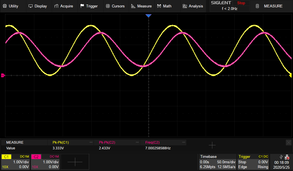
A Low pass filter has been added on each of the temperature input channels. The cut-off frequency is below what my oscilloscope can handle, but a plot in the time domain verifies a 7 Hz -3dB point.


